VB Program: Michelson and Morley's experiment
Introduction and Purpose
The purpose of the program "VB MMX" is to simulate the interference fringes of the Michelson and Morley's Experiment demonstating four different explanations:
- Without Length contraction and Without Time dilution (Shift)
- With Length contraction. (No shift)
- With Time Dilution (No shift)
- With both Length contraction and Time Dilution (Shift)
To get a copy select: VB MMX.zip
The program consists of 2 Forms: Control Form and Display Form
The Control Form is used to define the parameters of each simulation and to perform a simulation.
The most important parameter are the parameter Test and Sub Test. There are 7 basic tests or setup conditions implemented. When the parameter Test is modified the parameter Sub Test is changed to zero.
In order to perform a simulation the Push Button Calculate is used.
The Display Form consists of two sets of lines and a central part.
- The horizontal lines shows the waves which are reflected in the vertical direction. The mirror is towards the top.
- The vertical lines shows the waves which are reflected in the horizon direction. The mirror is towards the right.
- The central part show the interference fringes. It is important to observe the red dot in the center of the central part. This is point where a light signal in the horizontal direction and in the vertical meet each other.
It is possible to perform the simulation under 7 different setup conditions.
The parameters which define those setups are: distance d towards the mirrors, speed of light c, speed v, wave length lambda.
- test 1 performs a simulation under "laboratory" conditions.
c = 100 km/sec, v = 0, d = 100 cm, labda = 4 cm
The central part shows the interference fringes.
- test 2 is almost the same as test 1 i.e. a simulation under "laboratory" conditions.
v = 15 km/sec towards the right.
The display is shown for an observer which also has a speed of v = 15 km/sec.
The interference pattern is in the center.
- test 3 is almost the same as test 1 i.e. a simulation under "laboratory" conditions.
v = 15 km/sec towards the right.
The display is shown for an observer which has a speed of v = 0 km/sec.
If you compare test 2 and test 3 than the interference pattern of test 3 has an offset towards the right.
- test 4 is the real simulation. Similar as test 2.
c = 300000 km/sec, v = 60km/sec, d= 1100 cm and labda 5.9*10^-5 cm.
The observer has a speed of 60 km/sec.
- test 5 is identical as test 4, but now for different values of v. The simulation works like a movie, with 7 frames, each with a difference of 10 km/sec
- test 6 is the real simulation. Similar as test 3.
c = 300000 km/sec, v = 60km/sec, d= 1100 cm and labda 0,059 cm.
The observer has a speed of 0 km/sec
The simulation works like a movie, with 7 frames, each with a difference of 10 km/sec
- test 7 shows the experiment over a continuous angle of 90 degrees.
c = 300000 km/sec, v = 20000km/sec, d= 1100 cm
In order to observe
To demonstrate the four different explanations proceed as follows:
- First select test 4. Select Calculation. This is sub test 1.
This will demonstrate the MM experiment without Length Contraction and without Time dilution. The interference pattern will be shifted.
- Select Calculation again. This is sub test 2.
This will demonstrate the MM experiment with Length Contraction and and without Time dilution.
There is no interference pattern shift.
- Select Calculation again. This is sub test 3.
This will demonstrate the MM experiment without Length Contraction and with only Time dilution.
There is no interference pattern shift.
- Select Calculation again. This is sub test 3.
This will demonstatate the MM experiment with both Length Contraction and Time dilution. The interference pattern will shift.
- When Calculation is selected again all the 4 sub tests will be repeated.
If you want to see the same explanations but now in slow motion, like a movie, repeat those same steps but now using type 5.
The central part of the display also shows two white lines. Both lines represent the position of a wave at the same moment t1.
The horizontal white line represents the position of the wave at t1.
t1 = distance of light path in vertical direction divided by c
t1 = (2 * d / SQR(1 - v˛ / c˛) / c
t1 = 2*d/SQR(c˛-v˛)
t2 = distance of light path in horizontal direction (mirror towards the right) divided by c
t2 = d / (c - v) + d / (c + v)
t2 = 2*d*c/(c˛-v˛)
t2 is larger than t1
This means, in case no length contraction is considerd, that the vertical white line at t1 should be on the right side from the center of the display. This is the case with Sub Test 1
In case length contraction is considerd in horizontal direction, the distance d changes to:
d = d * SQR(1 - v˛ / c˛)
t21 = distance of light path in vertical direction divided by c now becomes:
t21 = t2 * SQR(1 - v˛ / c˛)
t21 = 2 *d * c/(c˛-v˛)*SQR(1 - v˛ / c˛)=2 *d * c/(c˛-v˛)*SQR(c˛ - v˛) / c
t21 = 2 *d /(c˛-v˛)*SQR(c˛ - v˛) = 2 *d / SQR(c˛ - v˛)
This means that t21 = t1
The means is that when length contraction is considerd, the two white lines should go through the same point.
In case time dilution is considered in horizontal direction the moment t1 is adjusted to t11.
t11 = t1 * 1 / SQR(1 - v˛ / c˛) = t1 * c /SQR(c˛ - v˛)
t11 = 2 * d/SQR(c˛-v˛)*c /SQR(c˛ - v˛) = 2 *d*c /(c˛ - v˛)
This means that t11 = t2
The means is that when time dilution is considerd, the two white lines should also go through the same point.
Operation Display
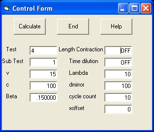 Figure 1
|
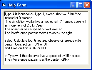 Figure 2
|
- Figure 1 shows the Control Form
The most important Push Button is called Calculate .
Selecting this command will execute one simulation or test.
The most important control parameter is called Test . Valid numbers are from 1 to 7. Selecting Calculate will execute this particular test.
- Figure 2 shows the Help Form of the control parameter Test
Picture 3
|
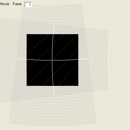
Picture 3 shows the results of the simulation of test 4. Test 4 is movie of 7 frames. Test 4 is a simulation of what is called a laboratory condition. In this situation the speed of light is small.
- When Picture 3 is not selected the display shows frame 1.
- When Picture 3 is selected the display shows frame 7.
The main difference between frame 1 and frame 7 is that the interference frame is moved towards the right. The operator does not move i.e. has a speed zero.
This is specific visible studying the reflection from Mirror 1 i.e. the horizontal mirror.
In frame 1 this reflection comes straight from above
In frame 7 the reflection comes also from above, but more towards the left.
|
  ------1-------

       . .

      .   .

     .     .        |
                    |
S...A.......X.......2
      --->    <---> |
        v    .      |

              M

   Picture 1
|
The Michelson and Morley's Experiment consists of:
- A Lightsource S of monochromatic light. A beam which frequency f and a wavelength Lambda.
- At point A there is a beamsplitter, which splits the beam in two directions: One in "vertical" directical and One in horizontal direction.
- At the same distance from point A there are two mirrors: One at point 1 in horizontal direction Mirror 1 and one at point 2 in vertical direction Mirror 2.
- Starting from point A the "vertical" beam is reflected at point 1 against Mirror 1 towards the direction at point X.
The beam in horizontal direction is reflected at point 2 against Mirror 2 towards the direction at point X.
- At point X the two beams combine and are reflected towards the point M where the interference patern is observed.
- The whole setup, including the source, has a speed v towards the right. It should be mentioned that in reality neither the speed v nor the direction is known.
|
The interference pattern is created from waves in two directions:
- First we have a beam which is reflected against mirror 1. In picture 1 this are the waves which are coming from the top towards the monitoring piece. For more detail See Picture 2 A.
- Secondly we have a beam which is reflected against mirror 2. In picture 2 this are the waves which are coming from the left. For more detail see picture 2 B.
t0....a.....a.....A...
t1---b-----b-----B----
t2++c+++++c+++++C+++++


t0....a.....A.....a...
t1---b-----B-----b----
t2++c+++++C+++++c-----


      Picture 2A
|
Picture 2A shows the reflection pattern in vertical direction. They are reflected via Mirror 1. That means the waves are comming from the top towards the bottom.
Picture 2A shows two sections of three lines above each other. Each section shows the position of the wave (the top) at three different moments identified with the letters a, b and c.
The line with the dots shows the position at t0. The line with the dashes at t1. The line with the + sign at t2. The position of the wave at t3,t4 and t5 are not shown. The wave length Lambda is the distance between two lines at the same moment.
In this particular case the number of lines between two sections is 6. This is the parameter cyclecount.
For type 1, 2, 3, 4 and 5 the parameter cyclecount is 10
|
    t2    t2    t2
     t1    t1    t1
      t0    t0    t0
    +|.   +|.   +|.
    +|a   +|a   +|A
    +b.   +b.   +B.
    c|.   c|.   C|.
    +|.   +|.   +|.
    +|.   +|.   +|.
    +|.   +|.   +|.
    +|a   +|A   +|a
    +b.   +B.   +b.
    c|.   C|.   c|.
    +|.   +|.   +|.
    +|.   +|.   +|.
     Picture 2B
|
Picture 2B shows the reflection pattern in vertical direction. They are reflected via Mirror 2. That means the waves are comming from the left towards the right.
Picture 2B shows three sections of three lines beside each other. Each section shows the position of the wave (the top) at three different moments identified with the letters a, b and c.
The line with the dots shows the position at t0. The line with the dashes at t1. The line with the + sign at t2. The position of the wave at t3,t4 and t5 are not shown. The wave length Lambda is the distance between two lines at the same moment.
In this particular case the number of lines between two sections is 6. This is the parameter cyclecount.
For type 1 and 2 the parameter cyclecount is 10.
|
    t2    t2    t2
     t1    t1    t1
      t0    t0    t0
    +|.   +|.   +|.
t0....a...+|a...+|A...
t1--+b----+b.----B----
t2++c+++++c|.+++C+++++
    +|.   +|.   +|.
    +|.   +|.   +|.
    +|.   +|.   +|.
t0....a...+|A...+|a...
t1--+b.---+B.----b----
t2++c|.+++C|.+++c+++++
    +|.   +|.   +|.
    +|.   +|.   +|.
     Picture 2C
|
Picture 2C shows the interference patern as a combination of picture 2A and picture 2B. This is a combination of the waves which are reflected via Mirror 1, coming from the top and the waves which are reflected via Mirror 2, coming from the left
Picture 2C shows a total of 5 waves. Two waves are reflected via Mirror 1 and three waves are reflected via Mirror 2. Each wave is shown are three different moments t0,t1 and t3.
The 5 lines with the dots shows the position at t0. The horizontal lines and the vertical lines meet each other at 6 positions. This are the points of maximum interference. They are indicated with the letters a and A.
The 5 lines with the "-" and "|" shows the position at t1. The horizontal lines and the vertical lines meet each other at 6 positions. This are the points of maximum interference. They are indicated with the letters b and B.
The 5 lines with the "+" show the position at t2. The horizontal lines and the vertical lines meet each other at 6 positions. This are the points of maximum interference. They are indicated with the letters c and C.
|
The reason what you see depents about the position of the beamsplitter, which makes an angle of 45 degrees with the horizontal line. If the beam splitter at the line indicated by the letters "ABC ABC" then that is what you see.
The reason why the interference pattern in some sense is frozen is because the whole apparatus including the operator is fixed on the surface of the earth.
In order to understand the interference pattern the beam is not a single line, but has a conic shape. The beam starts as a point but becomes wider at larger distances.
                                     .
                                          .D
                                     .    |
                                .         |
                           .              |
                      .                   | y
                 .                        |
            .                      |      |
       .      a1                   |      |
  A--------------------------------B------C
       .                           | -->  |
            .                      |  v   |
                 .
                      .
               Picture 3
|
- The point A is the origin at t=0 or t0. This is where the light beam starts in the direction of point D with speed c.
The angle DAC = a1
- The point B is the position of the mirror at t=0 or t0. The distance AB = d. The speed of the mirror is v.
- The lightbeam hits the mirror at point D at t1. At that moment the mirror is at point C.
- The distance AD = c*t1. The distance AB = d. The distance BC = v*t1. The distance CD = y. The distance AC = x
- At point D the beam is reflected back towards the position where it interferes with the beam which comes from the top. That part is not shown.
|
In order to calculate the reflection moment t1 for a specific angle "a1" we proceed as follow:
- The distance AC = x = AB + BC = d + v*t1.
- With tan(a1) =tna1 = y/x we get: y = tna1 * x
- Next we investigate the triangle ACD. We start with AD^2 = y^2+ x^2
- This gives: (c*t1)^2 = x^2*tna1^2 + x^2 = x^2(1+tna1^2) = (1+tna1^2)*(d+v*t1)^2 = beta * (d+v*t1)^2
- Combining the beginning with the end we get: c^2*t1^2 = beta*(d^2 + 2*d*v*t1 + v^2*t1^2)
- in total: (c^2-beta*v^2) * t1^2 - 2*d*v*beta * t1 - beta*d^2 = 0 :
- Using aa= C^2-beta*v^2: bb= -2*d*v*beta : cc = -beta*d^2 we get: aa*t1^2 + bb*t1 + cc = 0
- Finally we get: t1 = (-bb + sqr(bb*bb -4*aa*cc))/ (2*aa). Now we know t1
The central part of the display is the matrix ARRAY with consists of 170 by 170 pixels.
The program consists of two main sections.
In the first main section the horizontal set of lines are drawn (mirror towards the top) Each line represents the position of a wave at a certain moment. Each of those lines is in the same phase.
In the second main section the vertical set of lines are drawn (mirror towards the right). Those lines are also in the same phase
Each set of lines consists of primary lines (for example 3) and secondary lines.
The primary lines are at one wave length (lambda) distance apart.
In order to draw the interference pattern the program works as follow:
- First the program will draw the primary lines in the horizontal direction. For example 3.
Those lines are drawn in the color 7 (gray).
- Next the program draws the primary lines in the vertical direction. For example 3.
Those lines are also drawn in the color 7 (gray). However when at a certain position there
is already a gray dot the color will be white. At such we will get 9 white dots. At those positions the waves amplify each other (coincide).
- Next the program will clear all gray dots.
- Next the program will draw each of the secondary lines and the corresponding white dots in the same manner as explained above.
- When all the lines are drawn the program will display the interference pattern i.e. only the white dots.
In order to simulate the four different explanations two variables are used:LCONTRACT and TDILUTION.
The distance to the spiegel is controlled by three different parameters: DSPIEGEL, DSPIEGELX (horizontal) and DSPIEGELY (vertical). Initial are all the three the same.
When LCONTRACT is one DSPIEGELX (DSPIEGELXX) is modified with the factor SQR(1-v˛/c˛)
When TDILUTION is one the time variabel t or t0 is modified with the factor 1/SQR(1-v˛/c˛)
- The above simulation shows that the explanation for the Michelson and morley's experiment can be both length contraction or time dilution.
- The easiest physical explanation of the MM experiment is length contraction of the source.
The cause is the wave length genererated in the light source. As a result of the movement towards the right the wave length is shortened in the horizontal direction.
When the source moves towards the left (this means the speed v is negatif) the wave length increases in the horizontal direction.
In the vertical direction there is no change in wave length.
Feedback
None
Created:15 December 2000
Modified: 11 Augustus 2016
Modified: 6 May 2019
Back to my home page: Contents of This Document